What Is the Difference Between Control Cable and Instrumentation Cable Assemblies?
The main difference betwe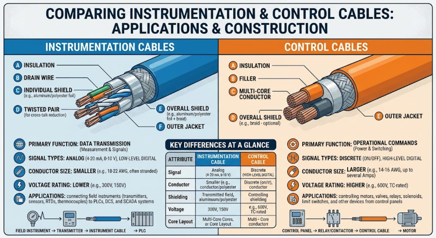 en control cable assemblies and instrumentation cable assemblies is the electrical function each supports. Control cables typically carry commands, switching signals, communication signals, or low-voltage operating power between controllers and equipment. Instrumentation cables are generally designed to transmit precise, low-level analog or digital measurement signals from sensors and instruments to monitoring or control systems.
The two categories can overlap in complex industrial systems, but their conductor size and arrangement, shielding, electrical characteristics, mechanical requirements, and testing needs often differ.
At Meridian Cable, we evaluate more than the label applied to a cable. We assess the complete electrical and mechanical application, including signal type, voltage, current, environment, motion, routing, interference risk, connector requirements, and production volume. This engineering-first approach helps us develop custom cable assemblies that support dependable communication between components in an OEM system.
Control Cable vs Instrumentation Cable: How Their Functions Differ
Control cables are commonly used to tell equipment what to do. These cables may connect programmable logic controllers, control panels, relays, switches, motors, actuators, valves, and other machine components.
A control circuit may send a start or stop command, change an operating mode, activate a device, transmit a communication signal, or provide operating power to a low-voltage component. Our custom control cable assemblies are engineered around the command, power, communication, and response requirements of the system.
Instrumentation cables are primarily used to carry information about what a process is doing. These cables often connect sensors, transmitters, meters, thermocouples, pressure devices, flow instruments, and data acquisition equipment.
The transmitted signal may represent temperature, pressure, speed, position, vibration, flow, or another measured condition. Because these signals can be small and sensitive to interference, the cable must preserve their accuracy as they travel to a controller, display, or monitoring device.
A simple way to understand the difference is:
- Control cables often carry instructions.
- Instrumentation cables often carry measurements.
Both may operate together in the same industrial system. An instrumentation cable might deliver a temperature reading to a controller, while a control cable carries the controller’s command to open a valve, activate a relay, or adjust a motor.
How Control Cable Assemblies Are Constructed
The construction of an industrial control cable assembly depends on the electrical load, number of circuits, installation conditions, and mechanical demands. A design may include multiple insulated conductors, conductor identification, drain wires, shielding, fillers, strain relief, protective jackets, and application-specific connectors.
Control cables may require larger conductors than instrumentation cables when they carry more current or provide operating power to a device. Other applications may require high-flex construction for moving equipment, oil-resistant jackets for factory environments, or rugged protection against abrasion, moisture, chemicals, and repeated handling.
These requirements are especially important when developing industrial control cable assemblies for automation equipment, machinery, control panels, and other demanding systems.
When a control cable is part of a terminated assembly, connector selection and pin mapping are just as important as the bulk cable. Meridian supports the complete interconnect through our cable assembly design and engineering services, including component evaluation, drawings, prototyping, tooling, process planning, and production documentation.
How Instrumentation Cable Assemblies Are Constructed
Instrumentation cable assemblies are usually designed around signal integrity. Common configurations include twisted pairs, triads, individual pair shielding, an overall shield, drain wires, and insulation and jacket materials selected for the signal, environment, and routing conditions.
Twisting helps reduce the effects of electromagnetic interference. Shielding can protect low-level signals from electrical noise generated by motors, drives, power wiring, radio-frequency sources, and other nearby equipment.
Cable capacitance, resistance, impedance, temperature rating, and shielding arrangement may influence whether the measured signal reaches the receiving device accurately. These factors become especially important with long cable runs, sensitive analog signals, high-speed digital communication, or installations with significant electromagnetic interference.
Instrumentation circuits may also require separation from power conductors. A cable that performs well on a clean test bench may perform differently when routed through a crowded industrial cabinet or alongside high-current equipment. The design must account for the actual operating environment rather than treating the cable as an isolated component.
Key Differences in Shielding, Conductors, and Signal Integrity
Shielding is one of the most important design considerations, although either cable type may be shielded. Instrumentation cables commonly use twisted, shielded pairs because low-level measurement signals can be particularly vulnerable to electrical noise.
Control cables may also require shielding when they carry communication signals, encoder feedback, variable-frequency drive controls, or commands in electrically noisy environments.
The correct shielding method depends on the interference source, system architecture, available space, grounding strategy, and mechanical requirements.
Foil shielding can provide high coverage with a relatively compact construction and is often paired with a drain wire. Braided shielding can provide mechanical durability, flexibility, and a low-resistance path to ground. Some assemblies use a combination of shielding methods.
Our shielded cable assemblies are designed around the interference risk, bend requirements, termination method, grounding strategy, and space available within the system.
Conductor size also tends to differ between the two cable categories. Control circuits that operate relays, solenoids, or powered devices may require conductors sized for higher current. Instrumentation circuits often prioritize the stable transmission of small signals and may use smaller conductors arranged in pairs or triads.
Neither assumption should replace an engineering review. Voltage drop, cable length, ambient temperature, flex life, connector limitations, and electrical performance requirements can all affect the correct conductor size and construction.
How to Choose Between Control and Instrumentation Cable Assemblies
The selection process should begin with the electrical function. Before choosing a cable, determine what it must carry, where it will operate, how it will be routed, and what a failure would mean for the system.
Important questions include:
- Is the circuit carrying a command, measurement, communication signal, or power?
- What voltage, current, frequency, and signal level are involved?
- Will the cable run near motors, drives, transformers, power conductors, or radio-frequency equipment?
- Does the application require twisted pairs, controlled impedance, shielding, or a drain wire?
- Will the cable assembly flex, coil, bend repeatedly, or remain stationary?
- What temperature, moisture, chemical, abrasion, flame, or regulatory requirements apply?
- Which connectors, terminals, pinouts, labels, and strain-relief features are needed?
- What testing and documentation must be completed before shipment?
- What production quantity and future volume requirements must the design support?
In many OEM projects, the most effective solution is not a generic cable selected from a catalog. A custom design can combine the correct conductors, shielding, jacket, connectors, breakouts, labels, and protective components in one repeatable assembly.
Meridian also provides custom cable assembly prototyping services to help clients evaluate fit, routing, termination, manufacturability, and performance before moving into volume production.
Testing and Manufacturing Requirements
Cable selection is only one part of reliable performance. The manufacturing process must consistently reproduce the approved design, especially when shielding, drain-wire termination, pair orientation, connector pinouts, and strain relief affect signal quality or functionality.
Every product Meridian manufactures is tested and retested for continuity, integrity, polarity, and functionality before shipment. Depending on the application, application-specific qualification testing may also evaluate environmental exposure, mechanical stress, repeated flexing, electrical performance, or other operating conditions.
Meridian’s Advanced Life Testing Lab supports validation for demanding applications where performance under real-world conditions must be evaluated before production.
Repeatable manufacturing also depends on controlled processes, accurate documentation, component traceability, and consistent workmanship. Learn more about Meridian’s cable assembly manufacturing capabilities.
Meridian Cable has manufactured custom cable assemblies and wire harnesses since 1994. We operate production facilities in St. Augustine, Florida, and Tanggu, China, providing access to domestic engineering support, international manufacturing capacity, and global logistics coordination.
Our cable manufacturing certifications include ISO 9001:2015 and IATF 16949, along with UL-approved manufacturing capabilities. These standards support disciplined production controls, documentation, quality management, and repeatable manufacturing.
Discuss Your Cable Assembly Requirements With Meridian
Choosing between a control cable assembly and an instrumentation cable assembly requires more than matching a product name to an application. The design must account for electrical function, signal sensitivity, current, routing, interference, motion, environmental exposure, connector requirements, testing, and production goals.
Some applications fit clearly into one category. Others require a custom assembly that combines control, instrumentation, communication, and power conductors within one coordinated interconnect.
Meridian works with OEM engineers, procurement teams, product designers, and operations leaders to define the quantity, application, environment, performance requirements, materials, budget, deadline, and production goals for each project.
Discuss your cable assembly requirements with Meridian’s design team to develop a dependable solution from initial concept through qualification and volume manufacturing.